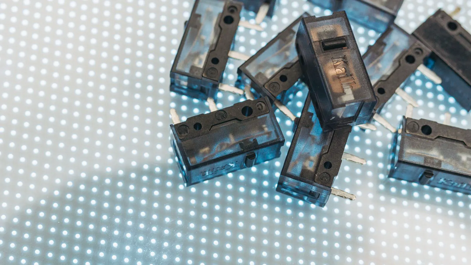
Use a 4-wire Kelvin setup to isolate lead resistance from the contact path. Measure voltage drop and current through the switch, then calculate contact resistance. Verify results with a low-current sweep and visual inspection.
- Use a 4-wire Kelvin setup to prevent lead resistance from skewing your contact resistance reading.
- Apply a low test current to avoid heating the contact and altering the material properties during the measurement.
- Check for oxidation and mechanical wear, which are common causes of unstable or elevated contact resistance.
- Repeat measurements at multiple positions to confirm the contact path is consistent throughout the switch travel.
Why Contact Resistance Matters in Switching Assemblies
Contact resistance is the measurable voltage loss that occurs when current passes through a metal-to-metal interface. Even a few milliohms can cause heat buildup, signal degradation, or premature failure in sensitive circuits. Engineers often overlook this because the resistance is far below the threshold of standard multimeters, yet it directly impacts electrical reliability over time.
In a low-current signal path, a contact resistance of 50 milliohms might seem negligible. However, if that path carries a pulse signal that switches rapidly, the impedance mismatch can reflect energy back into the driver. In a power application, the same 50 milliohms acting on a 10-ampere current produces a 500-millivolt drop and dissipates 5 watts of heat. That heat raises the temperature of the surrounding PCB substrate and can accelerate the aging of nearby electrolytic capacitors. The cumulative effect is a reduction in the lifespan of the assembly.
This guide walks through a step-by-step method to measure and verify contact resistance in switches. It assumes you have a basic understanding of DC circuit fundamentals and access to a low-current source or a programmable power supply. The focus is on practical, repeatable testing that can be integrated into incoming inspection or final acceptance testing.
What You Need Before Starting
Before touching a switch, confirm you have the right tools and conditions. A standard 3-wire multimeter will not give you the resolution you need. You need a setup that separates the current path from the voltage measurement path.
Gather the following:
- A 4-wire Kelvin probe set or a dedicated low-resistance tester
- A current source capable of outputting 10 to 100 milliamperes
- A digital multimeter or data acquisition system for voltage measurement
- A clean, dry workspace
- A reference switch known to be in good condition for calibration checks
- A magnifying lens or microscope for visual inspection
If your current source can only output variable current, set it to 25 milliamperes as a starting point. This level is high enough to produce a measurable voltage drop but low enough to avoid Joule heating in small contacts. For larger power contacts, you may push the current higher, but you must monitor the temperature rise. If the contact temperature exceeds the rated maximum of the material, stop the test.
Ensure your workspace is free of static discharge risks. Static electricity can damage sensitive control circuits inside the switch or create false readings if it jumps across the contact surface. Use an anti-static wrist strap if you are handling unshielded logic boards.
How to Set Up the Measurement
The core principle here is the Kelvin connection. You inject current through two outer wires and measure voltage across two inner wires that connect directly to the contact surfaces. This eliminates the influence of lead resistance and test lead contact resistance from your calculation.
Connect the current source to the two outer terminals of the switch. Connect the voltage leads of your meter to the two inner terminals. Ensure the voltage leads make solid contact with the same metal surfaces where the current enters and exits. If the switch has multiple contact points, test each one individually. Do not assume that a common ground pin provides the same electrical path as the specific contact under test.
If you are testing a relay or a multi-position switch, isolate the contacts you are measuring. Disconnect any parallel paths that might shunt current and skew your reading. A relay coil is an inductive load. If it remains energized during your DC contact test, the inductive kick can interfere with your voltage measurement. De-energize the coil completely before starting.
For switches with spring-loaded contacts, apply the correct actuation force. Testing a switch without closing it against its spring, or with excessive force that deforms the contact, will yield results that do not reflect normal operation. If the switch is designed to be operated by a finger, use a mechanical fixture that replicates that force.
Step-by-Step Measurement Procedure
Follow these steps in order. Each step has a specific reason, and skipping one can invalidate the result.
- Zero your meter. Short the voltage leads together and set the meter to zero. This removes offset error from your reading.
- Verify the current source output. Measure the actual current flowing through the switch using a shunt resistor or an inline ammeter. Do not trust the source display alone. A current source drifts over time, especially if it is a bench unit that has been running for a long period.
- Connect the Kelvin leads. Place the voltage sense leads on the contact surfaces. Avoid touching the housing or any non-conductive material. If the contact area is small, use a needle probe or a fine-tip sense lead to ensure the electrical path is direct.
- Apply the current. Set the current source to your target value, typically 25 to 50 milliamperes. Allow a few seconds for the reading to stabilize. The metal contact needs time to reach thermal equilibrium.
- Record the voltage drop. Read the voltage across the sense leads. This value will be in millivolts. If the reading is unstable, check for air gaps or loose mechanical connections.
- Calculate contact resistance. Divide the measured voltage by the known current. For example, if you measure 0.5 millivolts at 25 milliamps, the contact resistance is 0.02 ohms or 20 milliohms. Keep the units consistent throughout your calculation.
- Test at multiple positions. If the switch has a travel range, measure at the mid-position, the fully open position, and the fully closed position. Some switches have higher resistance at the beginning of the travel due to contact alignment. A rotary switch, for instance, may have a dead zone where the contacts do not fully engage.
- Repeat the measurement three times. Switch the current direction between runs to cancel out any thermoelectric effects at the probe contacts. Thermoelectric voltages can be in the millivolt range and will add a fixed offset to your reading if you do not average out the polarity.
Common Mistakes That Skew Your Results
Engineers who have done this before know that the method is simple, but the execution is where errors creep in.
- Using a 3-wire setup. A standard multimeter in ohms mode includes the resistance of the test leads and the contact between the probe tip and the part. This can add several milliohms of error, which is larger than the actual contact resistance you are trying to measure. For a 5-milliohm contact, a 3-wire measurement might show 10 milliohms or more, masking the true performance.
- Applying too much current. If you use an ampere-level current to force a larger voltage drop, the contact will heat up. Heating changes the resistance of the contact materials and can even cause permanent deformation in soft alloys. Always check the datasheet for the maximum continuous current rating of the specific contact material.
- Poor sense lead placement. If your voltage leads are not on the same metal surface as the current path, you are measuring the resistance of the wire between the current entry point and your sense lead. That is not the contact resistance. The sense leads must touch the metal that the current actually flows through.
- Ignoring oxidation. A thin film of oxide on a silver or nickel contact can add significant resistance. If the reading is unstable or higher than expected, clean the contact with a dedicated contact cleaning wipe, not a solvent that leaves residue. Residue creates a dielectric layer that increases resistance and can cause arcing later.
- Testing in a humid environment. Moisture on the contact surface can create a conductive path that bypasses the intended contact area or adds a variable resistance in parallel. High humidity can also cause condensation on the probe tips, leading to erratic readings.
How to Interpret the Data
Once you have your readings, compare them to your acceptance criteria. If you do not have a defined spec, use the following general approach.
| Condition | Typical Contact Resistance Range | Action |
|---|---|---|
| New silver contact | 5 to 20 milliohms | Pass |
| New gold contact | 10 to 40 milliohms | Pass |
| Worn nickel contact | 50 to 150 milliohms | Investigate wear |
| Oxidized copper contact | 200 milliohms or higher | Clean or replace |
These ranges are general. Actual values depend on the contact area, the force applied, and the specific alloy used. Gold contacts are preferred in low-current signal switching because they resist oxidation. Silver contacts have lower resistance but can tarnish in sulfur-rich environments. Copper contacts are common in power switching but require regular cleaning.
A single high reading is a warning. A consistent high reading across multiple positions indicates a problem with the contact materials or the mechanical alignment. A reading that changes between the two current directions suggests thermoelectric effects or a loose connection at the test point.
Consider the history of the component. A switch that has been cycled thousands of times will naturally have higher contact resistance than a new one. If the resistance has increased by more than 20 percent from its initial value, the contact is likely wearing out. Track these values over time if you are monitoring the long-term reliability of a critical system.
Final Verification and Documentation
The last step is to close the loop. Do not just record the number and move on.
Perform a visual inspection under magnification. Look for pitting, discoloration, or material transfer. A switch that measures low in resistance but shows pitting may fail soon as the contact area degrades. Pitting often occurs where arcing has occurred, usually during a high-current switch-on event. The material transfer, where metal from one contact sticks to the other, can create a short circuit or a high-resistance path.
Document the test current, the voltage reading, the calculated resistance, the contact position, and the ambient temperature. If your facility uses a test management system, log the data with a timestamp and the instrument serial numbers. This creates an audit trail that supports electrical reliability reviews.
Finally, run a quick functional test. If the switch is part of a larger assembly, verify that the circuit performs as expected after your contact resistance test. Cleaning or handling the contacts can sometimes dislodge debris, so a post-test functional check is a good habit.
If you are integrating this into an incoming inspection process, consider pairing it with a visual check of the contact materials. Knowing whether the contacts are silver, gold, or nickel helps you set the right acceptance thresholds and interpret anomalies correctly.
Frequently asked questions
Can I measure contact resistance with a standard multimeter in ohms mode?
No. A standard multimeter adds the resistance of its test leads and probe contacts to the reading. For milliohm-level measurements, you must use a 4-wire Kelvin setup to isolate the contact path.
What current should I use for the test?
Use a low current, typically between 10 and 100 milliamperes. This level is high enough to measure the voltage drop but low enough to avoid heating the contact and altering the material properties.
Why do I need to reverse the current direction between measurements?
Reversing the current helps cancel out thermoelectric voltages that can develop at the probe-to-part junctions. These voltages can be in the millivolt range and add error to your low-resistance reading.
How do I know if the contact is oxidized?
Oxidized contacts often show a higher resistance than expected, unstable readings, or visible discoloration. Cleaning with a proper contact cleaner and re-measuring can confirm if oxidation was the cause.
Does the ambient temperature affect the reading?
Yes. Metal resistance changes with temperature. While the effect is small at room temperature variations, it can matter in precision applications. Record the ambient temperature and keep it stable during the test.