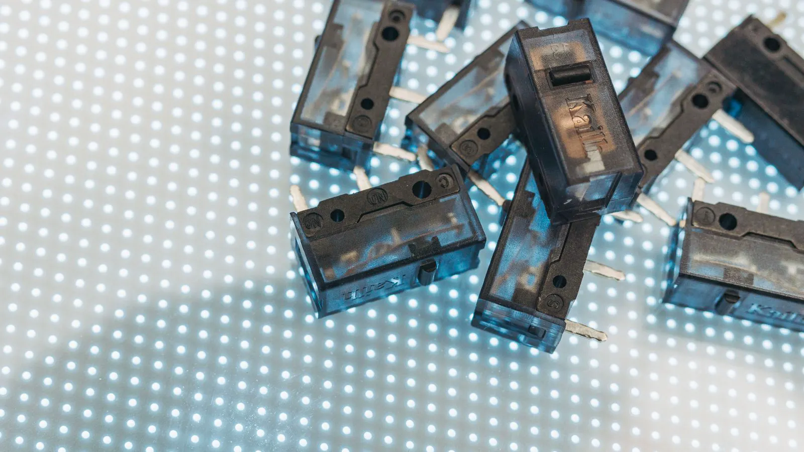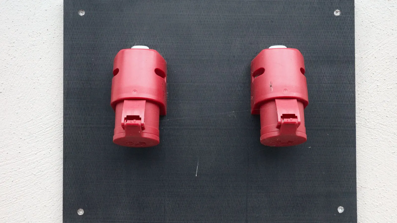
A reliable connector inspection involves checking mechanical fit, contact resistance, pin alignment, and environmental sealing. This checklist provides practical visual and functional tests for importers and quality managers to prevent field failures and ensure long-term performance.
- Visual checks for pin alignment, corrosion, and mechanical damage catch most reliability issues early.
- Functional tests for contact resistance and insulation resistance verify electrical performance under controlled conditions.
- Environmental verification, including sealing and strain relief, is critical for connectors used in harsh conditions.
- Documenting findings and maintaining traceability supports quality control and supplier management.
- Standardized inspection procedures reduce variability and help identify recurring defects across batches.
What to Check Before You Open the Box
Start with the packaging and the part itself. Open the carton and count the units. A missing count is a red flag that points to poor handling or a shipping error. Pull a sample from the top, middle, and bottom of the stack. Do not rely on the first few units. The top of a stack often receives the most damage during handling. The bottom units may have absorbed moisture from the pallet or the floor. By sampling all three layers, you get a representative view of the entire lot. If the count is off by even one unit, assume the carton was disturbed. Check for crushed corners, punctures, or torn tape. These signs suggest the contents were exposed to the elements.
Look at the connector housing. Check for cracks, sharp edges, and discoloration. The material should match the specification. A connector specified for nylon may arrive with a brittle resin that cracks during mating. If the housing feels soft or the color is off, set the sample aside. Nylon has a specific color and texture. If the housing is translucent where it should be opaque, or if it snaps when you bend it slightly, the polymer compound is wrong. The wrong compound affects thermal stability and mechanical strength. A connector that fails in the field often fails because the housing did not withstand the thermal cycling or the mating force.
Check the documentation. The packing list should match the purchase order. The datasheet should identify the part number, mating cycle, and environmental rating. If the part number does not match the drawing, stop the inspection. A wrong part number means a different pinout, a different dielectric, or a different contact force. Look for the date code on the packaging. Some manufacturers use a date code to indicate the production date. If the date is outside the expected shelf life, request a report on storage conditions. Connectors can degrade even in storage if they are exposed to high humidity or temperature.
Mechanical Fit and Pin Alignment
Mechanical fit is the first line of defense. A connector that does not seat properly will not make reliable electrical contact. Hold the connector and its mating part. Push them together with light pressure. They should align without forcing. If you have to tilt or twist to make them meet, the tolerances are out of spec. This usually happens when the molding process shifted the keying features. A small shift of a fraction of a millimeter can prevent the connector from fully seating. In a production line, this causes jams and rejects. In the field, it causes poor contact and increased failure rates.
Check the pins. Look for bent pins, shorted pins, and missing pins. Use a flashlight and a magnifying glass. A pin that leans outward even by a few degrees can cause intermittent contact. A pin that is too long may damage the mating contact. A pin that is too short may not reach the contact point. Pins that are too long often come from a molding issue where the pin length is not controlled. Pins that are too short may not make contact with the spring in the mating connector. If the pin is missing, check the cavity in the housing. Sometimes the pin is stuck in the molding process and has not been ejected. This leaves an empty hole in the connector.
Inspect the keying feature. Most reliable connectors use a key, a pin, or a notch to prevent mis-mating. The key should be present and aligned. If the key is worn or broken, the connector can mate at the wrong angle. This creates high stress on the contacts and increases the risk of arcing. Mis-mating is dangerous. If a high-voltage pin mates with a low-voltage pin, the insulation may break down. This can cause a short circuit or a fire. Check the keying feature on both the male and female connectors. One side may be damaged while the other is fine.
Check the mating force. You should feel consistent resistance. If the connector feels too loose, the shell may be worn. If it feels too tight, the housing may be deformed. Both conditions indicate a problem. Use a calibrated force gauge if you have one. Measure the force required to mate the connector. Compare the reading to the specification. If the force is below the minimum, the contacts may not spring together properly. If the force is above the maximum, you may damage the housing or the pins.
Electrical Contact Resistance and Continuity
Contact resistance is a direct measure of how well the connector carries current. A high resistance point creates heat. Heat degrades the contacts. It also increases the risk of fire in high-current applications. Measure the resistance at low current. High current can damage the contacts or the meter. Use a low-resistance ohmmeter or a micro-ohm meter for high-current connectors. The meter should be calibrated. Use a four-wire measurement method to eliminate the resistance of the test leads. Connect the probes directly to the pins. Do not use the test leads to measure the resistance.
Measure the resistance across each pin pair. Compare the reading to the specification. The value should be low and consistent. If one pin reads significantly higher than the others, that contact is suspect. A high resistance pin may be caused by oxidation, a bent pin, or a poor plating. Oxidation is common in high-humidity environments. It forms a thin layer of metal oxide on the contact surface. This layer increases the resistance. A bent pin reduces the contact area. A poor plating may not make good contact.
Check for short circuits. Measure between pins that should be isolated. The reading should be very high. If you see a low reading, there is a bridge or a damaged insulation. This can cause a circuit to fail or trip a protection device. A bridge is a thin film of metal or conductive material that connects two pins. It can be caused by a manufacturing defect or by contamination. Damaged insulation can also create a short. Check the insulation around each pin. Look for cracks or voids.
Test the ground pin if the design includes one. The ground connection should be continuous and low resistance. A broken ground path can cause noise problems and safety hazards. A broken ground pin can cause the circuit to float. This can lead to erratic behavior. It can also cause a shock hazard if the ground is the only protection. Measure the ground pin to the chassis. The resistance should be very low.
Insulation and Dielectric Integrity
The dielectric material prevents current from leaking between pins. Check the dielectric for cracks, voids, and contamination. A crack can create a path for moisture. Moisture lowers the insulation resistance. Insulation resistance is the measure of how well the dielectric prevents current from flowing. It is measured in megohms. A high insulation resistance indicates a good dielectric. A low insulation resistance indicates a problem.
Measure the insulation resistance between conductors. The value should be high, typically in the megohm range, depending on the design. If the reading is low, the dielectric is compromised. Use a high-voltage insulation resistance tester. Apply a voltage higher than the operating voltage. Measure the resistance. If the resistance drops over time, the dielectric is absorbing moisture. This is a sign of a long-term failure.
Check the creepage and clearance distances. These are the physical gaps between conductive parts. They must meet the design requirement for the operating voltage. Creepage is the distance along the surface. Clearance is the distance through the air. If the connector has been modified or the dielectric is damaged, the clearance may be reduced. A reduced clearance can cause arcing. Arcing damages the contacts and the dielectric. It can also cause a fire.
Look for dust, flux, or other contaminants on the contacts. These materials can degrade over time and create leakage paths. A clean connector is a reliable connector. Check the contacts with a magnifying glass. Look for residues. Flux residue is common in soldered connections. It can attract moisture. It can also cause corrosion. A clean connector should have no visible residue.
Environmental Sealing and Strain Relief
Reliable connectors must survive their environment. If the connector is rated for outdoor use, it must resist moisture, dust, and temperature swings. The environment includes the temperature range, the humidity, and the presence of contaminants. A connector rated for outdoor use must be tested in the field. A connector that passes the lab test may fail in the field.
Check the gasket or O-ring. It should be intact, uncompressed, and free of nicks. A damaged gasket will not seal. Water can enter the connector. Water causes corrosion and short circuits. A gasket that has been compressed and not returned to its original shape will not seal. This is called compression set. Compression set happens when the gasket is squeezed for a long time. It usually happens during mating or during storage. Check the gasket with your fingers. It should be soft and springy. If it is hard or flat, it is damaged.
Inspect the strain relief. The cable entry point is a weak link. The cable should be secured so that vibration and bending do not pull on the pins. A connector without proper strain relief will fail at the cable entry point. The strain relief holds the cable in place. It also protects the cable from being pulled out. Check the strain relief for cracks. A cracked strain relief will not hold the cable. It will allow the cable to pull out. This can cause a broken pin or a short circuit.
Check the thread sealant. If the connector uses a threaded interface, the sealant should be present and even. Too little sealant allows ingress. Too much sealant can block the seal path. Sealant is used to prevent moisture from entering the threaded interface. It also prevents vibration from loosening the threads. Check the thread with a flashlight. Look for a thin, even layer of sealant. If the sealant is missing or uneven, the seal is compromised.
For connectors rated for submersion, verify the IP rating. A connector rated for a high IP level should have a clear seal at all interfaces. If the seal is compromised, the rating is invalid. The IP rating is a standard for protection against dust and water. The first number is the dust protection. The second number is the water protection. A connector with a high IP rating must be tested in a water bath. If the seal is compromised, the connector may pass the lab test but fail in the field.
Visual and Surface Finish Checks
The surface finish protects the metal contacts. A reliable connector should have a consistent, even finish. The finish prevents corrosion and wear. It also improves the electrical contact. Check the finish with a magnifying glass. Look for scratches, pits, or discoloration. A scratch in the finish exposes the base metal. The base metal may corrode or wear quickly. A pit in the finish is a weak point. It can crack under stress.
Check for corrosion. Look for green, white, or black discoloration. Corrosion increases contact resistance and can cause failure. If you see corrosion, the storage conditions were poor or the part is damaged. Corrosion is a sign of moisture exposure. It happens when the metal is exposed to air and water. It is more common in high-humidity environments. A corroded pin will not make good contact. It may also cause a short circuit.
Check the plating. If the contacts are plated, the plating should be uniform. Look for bare spots, scratches, or peeling. A scratch in the plating exposes the base metal. The base metal may corrode or wear quickly. A bare spot is a place where the plating did not cover the base metal. It is a weak point. A peeling plating is a place where the plating has lifted off the base metal. It is a sign of poor adhesion.
Inspect the dielectric for scratches. A scratch in the dielectric can create a stress point. It can also reduce the clearance. If the dielectric is scratched, the connector may fail under thermal cycling. A scratch in the dielectric is a weak point. It can crack under stress. It can also reduce the insulation resistance. A scratched dielectric is a sign of poor handling.
Check the labeling. The part number and revision should be legible. If the label is faded or missing, you cannot verify the part. Do not use a connector you cannot identify. A faded label is a sign of poor storage. It can happen if the label is exposed to heat, light, or chemicals. A missing label is a sign of poor quality control. It means the part was not checked before shipping.
Documentation and Traceability
A reliable connector inspection is not complete without documentation. Record the lot number, the date, and the inspector. Record the test results. Keep the sample parts for reference. The lot number is a unique identifier for the batch of parts. It allows you to trace the parts back to the supplier. The date is the date of the inspection. It allows you to know when the parts were checked. The inspector is the person who performed the inspection. It allows you to know who checked the parts.
Use a standardized form. A consistent form reduces errors. It also makes it easier to compare results across batches. A standardized form includes all the required fields. It includes the part number, the lot number, the date, the inspector, and the test results. It also includes a space for notes. A consistent form ensures that all parts are checked in the same way. It also makes it easier to find missing information.
If you find a defect, quarantine the affected lot. Do not return defective parts to the pool. Track the defect to the supplier. A defective part is a risk. It can cause a failure in the field. It can also cause a safety hazard. A defective part must be removed from the pool. It must be quarantined. It must be tracked. A defective part must be returned to the supplier for analysis.
Keep the purchase order, the packing list, and the test report together. If there is a problem in the field, you need to trace the issue back to the source. A purchase order is a document that shows what was ordered. A packing list is a document that shows what was shipped. A test report is a document that shows what was checked. Keeping these documents together makes it easier to trace the issue back to the source. It also makes it easier to prove that the parts were checked.
Common Red Flags
- Pins that are bent, short, or missing.
- Housing cracks or sharp edges.
- Gasket nicks or compression set.
- Corrosion or plating defects.
- Insulation resistance below specification.
- Mating force that is too loose or too tight.
- Missing or faded part numbers.
If you see any of these red flags, stop the inspection. Do not proceed to the next stage. A red flag is a sign of a problem. It means the part may not be reliable. It means the part may fail in the field. A red flag must be investigated. It must be documented. It must be tracked. A red flag is a sign of poor quality. It is a sign of poor handling. It is a sign of poor storage.
How to Use This Checklist
Print the checklist. Use it for incoming inspection. Use it for pre-shipment inspection. Keep a copy in the quality file. A checklist is a tool. It helps you to check the parts in a consistent way. It helps you to find defects. It helps you to document the results. A checklist is only as good as the people who use it. A checklist is only as good as the training they receive. A checklist is only as good as the time they take to use it.
Train your team on the checklist. Make sure they understand what to look for and what to measure. A checklist is a tool. It helps you to check the parts in a consistent way. It helps you to find defects. It helps you to document the results. A checklist is only as good as the people who use it. A checklist is only as good as the training they receive. A checklist is only as good as the time they take to use it.
Review the checklist periodically. Update it when you see new defects. Update it when you change suppliers or specifications. A checklist is a living document. It must be updated as the parts change. It must be updated as the suppliers change. It must be updated as the specifications change. A checklist that is not updated is a checklist that is not useful. It is a checklist that is not reliable. It is a checklist that is not safe.
Final Thoughts
A reliable connector is built, not found. The inspection process verifies that the part meets the design. It catches defects before they reach the field. It supports quality control and supplier management. Use the checklist every time. Do not skip steps. Do not rely on appearance alone. Measure the performance. Document the results. Keep the records. A reliable connector is a result of good design, good manufacturing, and good inspection. It is a result of good documentation and good training. It is a result of good quality control and good supplier management.
Frequently asked questions
How often should I inspect a connector?
Inspect every incoming lot. If the connector is used in a critical application, inspect a sample during production. Do not rely on a one-time check.
What is the most common defect in connectors?
Bent pins and corrosion are among the most common defects. Both can be caught with a visual inspection and a low-resistance test.
Can I use a connector if the housing is cracked?
No. A cracked housing can allow moisture ingress and reduce mechanical strength. The connector should not be used.
How do I measure contact resistance?
Use a low-resistance ohmmeter. Connect the leads to the pins and measure the resistance. Compare the reading to the specification.
What should I do if I find a defect?
Quarantine the lot. Record the defect. Notify the supplier. Do not return the defective parts to the pool.