BJT overheating usually stems from poor thermal design, incorrect biasing, or component degradation. This guide identifies symptoms, isolates root causes, and outlines fixes to stop transistor failure in amplifier circuits.
- BJT overheating often starts with incorrect biasing or insufficient heat sinking.
- Check for shorted junctions and high emitter current before replacing components.
- Thermal paste and mechanical contact are as critical as electrical design.
- Monitor voltage drops across resistors to catch runaway currents early.
- Proper ventilation and component derating extend the life of sensitive stages.
A BJT overheating fault stops production lines and ruins prototypes. Engineers often blame the transistor first, but the root cause usually lives in the biasing network or the thermal path. The junction temperature rises until the silicon degrades or the collector-emitter voltage collapses. This guide walks through the symptoms, isolates the likely causes, and provides the fixes used in the field.
What symptoms indicate a thermal problem
Thermal issues rarely announce themselves with a single alarm. They appear as a cluster of related faults. The first sign is often a hot-to-the-touch PCB, usually near the emitter or collector pins. The second is a sudden shift in operating point. The output DC voltage drifts away from the mid-rail. The third is a change in gain. The stage may sound distorted or show a lower voltage gain than designed.
A common failure mode is thermal runaway. As the temperature rises, the leakage current increases. This pulls more base current from the bias network. The transistor conducts harder and heats up faster. The loop continues until the device fails or the power supply trips. If you see a transistor that stays hot after the circuit has been off for a few minutes, suspect a shorted junction or a failed base resistor.
Look closely at the audio output or signal waveform. A thermal fault often manifests as a soft clipping effect before any hard failure occurs. The distortion usually increases as the temperature climbs. This behavior distinguishes thermal issues from simple amplifier gain errors. A gain error remains constant regardless of temperature. A thermal fault shifts. The output voltage may drift upward or downward depending on the bias configuration. In a common emitter stage, a shift toward saturation lowers the collector-emitter voltage. In a common base configuration, it may push the collector current into the cutoff region.
Check the power supply rails. Thermal problems often correlate with supply current draw. If the supply current increases as the board heats up, the fault is internal to the stage. If the current remains stable but the output drifts, the issue may be in the feedback network or the sensor input. A multimeter set to measure millivolts can reveal a slow drift that a visual inspection misses.
How to identify the root cause
Start with the electrical side. Measure the base-emitter voltage and the collector-emitter voltage. Compare these against the datasheet specifications. If the collector current is high, the problem is likely in the biasing. The base resistor may have drifted up, or the emitter resistor may have drifted down. A high emitter current forces more power into the silicon.
Next, check the thermal path. The heat sink must have good contact. Oxidized surfaces or dried-out thermal paste increase thermal resistance. The fins must be clean. Dust and flux residue block airflow. If the heat sink is small, even a small increase in power can push the junction temperature past the limit.
Use a thermal camera or a non-contact thermometer to map the board. Look for hot spots that do not match the expected power dissipation profile. A healthy transistor in a power stage should be warm, not hot. If a specific pin is significantly hotter than the others, suspect a short or a high-resistance solder joint. A cold solder joint at the collector can create a localized resistive element. This generates heat at the interface rather than in the die.
Inspect the bias network with a multimeter. Measure the base resistor value out of circuit. Compare it to the schematic. If the value has drifted by more than 10 percent, replace it. Drift is common in carbon composition resistors and older metal film parts. Modern wire wound resistors are more stable but can still drift due to heating. Check the emitter resistor as well. A lower emitter resistance than designed reduces the negative feedback. This allows the base current to increase, driving the collector current higher.
Check the supply voltage. If the supply is unregulated or has poor filtering, voltage spikes can occur. These spikes increase the collector-emitter voltage. Since power dissipation is the product of current and voltage, a higher voltage doubles the heat generated for the same current. Measure the supply under load. Look for ripple or spikes. A noisy supply can cause intermittent overheating that only appears during peak load conditions.
Troubleshooting table for common BJT faults
Use this table to match symptoms to fixes. It covers the most frequent issues seen in amplifier stages.
| Symptom | Likely cause | What to do |
|---|---|---|
| Transistor is hot but circuit is off | Shorted collector-emitter junction or base-emitter short | Replace the transistor. Check for solder bridges or moisture damage. |
| Output DC voltage drifts upward | Base resistor drift or emitter resistor drift | Measure resistor values. Replace drift components. |
| Distortion with increasing gain | Thermal runaway from poor heat sinking | Improve heat sink contact. Add ventilation. Reduce bias current. |
| Intermittent failure after cooling | Thermal paste failure or loose thermal screw | Clean and reapply thermal paste. Torque thermal screws to spec. |
| High base current draw | Leaky base-emitter junction | Replace the transistor. Check for contamination on the PCB. |
| Collector current spikes | Supply voltage spike or failed bypass capacitor | Add a TVS diode. Replace the bypass capacitor with a low-ESR part. |
Practical fixes for thermal management
Thermal management is a mechanical and electrical problem. The electrical design must limit the power dissipated at the junction. The mechanical design must move that heat away. For low-power stages, a small heat sink or a copper pad on the PCB can work. For higher power, use a dedicated heat sink with fins.
Thermal paste is a filler, not a fix. It fills the microscopic gaps between the die and the heat sink. If the mounting surface is scratched or the heat sink is bent, the paste will not compensate. Clean the surface with isopropyl alcohol. Ensure the mounting screw is straight. Torque it to the manufacturer’s recommendation. Over-torquing can crack the die. Under-torquing leaves air gaps.
Airflow matters. A heat sink in a closed enclosure needs a fan. Natural convection works fine for a few watts, but it fails when ambient temperature rises. If the enclosure is in a hot environment, derate the transistor. Run it at a lower power level to keep the junction temperature within safe limits.
Consider the material of the heat sink. Aluminum is lightweight and cost-effective. Copper conducts heat better but is heavier and more expensive. For high power applications, copper heat sinks are preferred. For low power, aluminum is sufficient. The surface area of the fins is critical. A heat sink with many thin fins rejects heat better than a solid block of the same mass. However, thin fins are easy to bend. Inspect the fins for damage. A bent fin reduces the effective surface area and traps hot air.
Use thermal interface material correctly. Apply a thin layer, not a thick glob. A thick layer acts as an insulator. It traps air and increases the thermal resistance between the die and the heat sink. A thin layer fills the microscopic gaps without adding significant resistance. Clean the surface thoroughly before application. Any residue of old paste or flux increases the thermal resistance. Use isopropyl alcohol and a lint-free cloth.
How to prevent transistor failure in future designs
Prevention is cheaper than repair. Start with the schematic. Choose a transistor with a voltage and current rating above your maximum operating point. Add a margin of at least 20 percent. This margin absorbs component drift and manufacturing variation.
Use a current limit resistor in the emitter. This resistor sets the current and provides a voltage drop. If the resistor gets hot, you know the current is high. A failed emitter resistor can cause the transistor to conduct fully. This is a common cause of sudden failure.
Derate the power supply. If the supply can spike, the transistor sees a higher voltage. The power dissipation is proportional to the voltage squared. A small spike can double the heat. Add a series resistor or a TVS diode to clamp the voltage.
Review the layout. Keep the base and emitter traces short. Long traces pick up noise and inductance. This can cause oscillation, which adds heat. Route the high current paths wide. A narrow trace acts as a resistor. It heats up and adds to the total power loss.
Select the transistor based on the application. A general purpose transistor may not be suitable for high frequency or high power applications. For power amplifiers, use a power transistor with a low saturation voltage. A low saturation voltage reduces the voltage drop across the transistor when it is on. This reduces the power dissipation in the on state. For switching applications, use a fast switching transistor. Fast switching reduces the time the transistor spends in the linear region. The linear region generates the most heat.
Check the datasheet for the maximum junction temperature. This is the limit. Do not operate at the limit. Leave a margin. If the ambient temperature is high, the junction temperature will be higher. Use the thermal resistance rating to calculate the worst case scenario. Measure the thermal resistance from the junction to the case. Measure the thermal resistance from the case to the ambient. Add them together. This gives the total thermal resistance. Multiply by the power dissipation to find the temperature rise. Add this to the ambient temperature to find the junction temperature.
When to replace the part
Sometimes the transistor is the only issue. The biasing is correct. The thermal path is good. The power is within spec. Yet the part is hot. This usually means the die is damaged. The leakage current is higher than the datasheet limit. The part may have been stressed during assembly. A soldering iron left too hot can degrade the bonds. A static discharge can damage the oxide.
If you suspect damage, replace the part. Do not try to repair it. The internal bonds are not accessible. A new part with the same part number should solve the problem. If the new part fails immediately, the fault is in the circuit, not the part. Re-check the biasing and the thermal path.
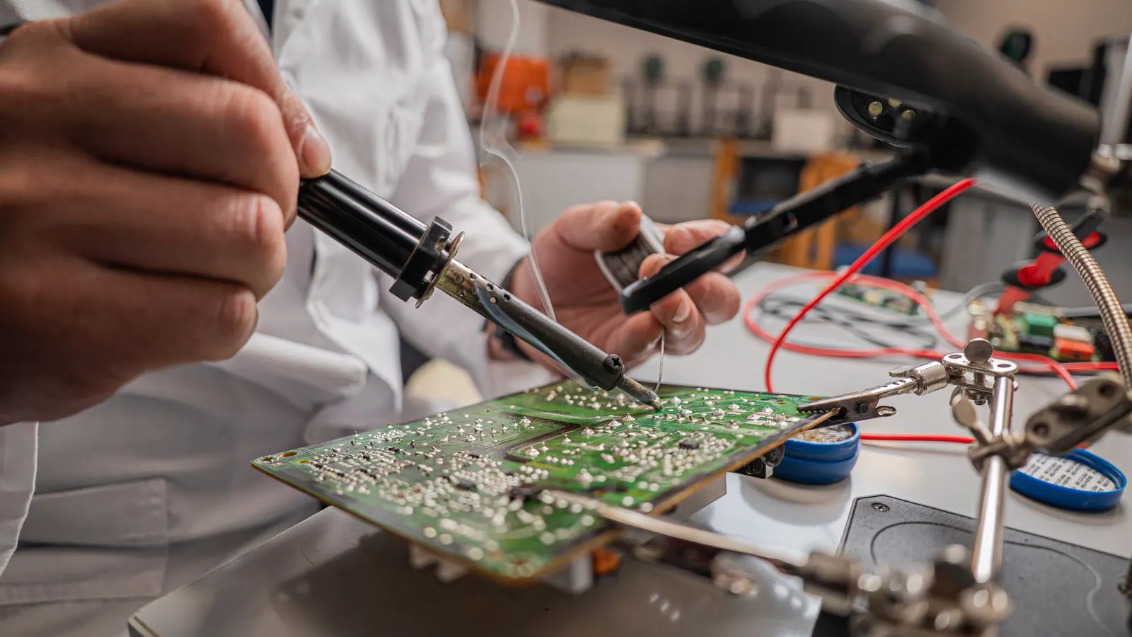
Inspect the PCB for damage. Look for discolored areas around the transistor. Discoloration indicates excessive heating. Check the solder joints. A cracked joint can cause intermittent contact. This creates a high resistance path. The resistance generates heat. Re-solder the joint. Use a clean tip. Apply enough heat to flow the solder but not so much that you damage the pads.
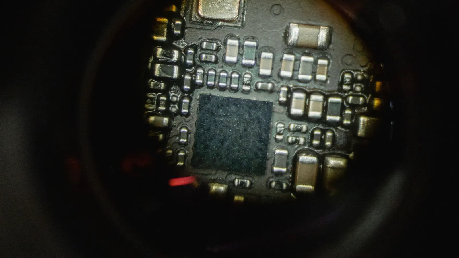
Check for contamination. Flux residue can attract moisture. Moisture can cause leakage paths across the PCB surface. This leakage can bypass the bias network. Clean the PCB with isopropyl alcohol. Inspect under a microscope if necessary. Look for tiny cracks or bridges.
Common mistakes to avoid
Engineers often make the same mistakes with BJT stages. The first is ignoring the power rating. A transistor rated for 1 watt is not safe for 1.5 watts, even if the datasheet says it can handle it. The second is using a heat sink that is too small. A small heat sink reaches equilibrium temperature quickly. It cannot reject heat when the ambient temperature rises.
The third mistake is poor biasing. A fixed bias circuit is sensitive to temperature. The base-emitter voltage drops by a few millivolts per degree. This shifts the operating point. Use an emitter resistor to stabilize the bias. The fourth mistake is neglecting the PCB. A thin copper pad acts as a heat sink. If it is too small, the transistor heats up. Add a thicker copper layer or a via to the ground plane to spread the heat.
Avoid using a heat sink without a mounting screw. A heat sink held by pressure alone will not maintain good contact. The screw provides the clamping force needed to compress the thermal interface material. Use a spring washer if the mounting surface is uneven. This helps maintain contact over the entire surface.
Do not ignore the ambient temperature. A heat sink that works fine in a cool room will fail in a hot car. Measure the ambient temperature in the operating environment. Derate the power accordingly. If the ambient temperature is 40 degrees Celsius, the junction temperature will be much higher than if the ambient is 25 degrees Celsius.
Check the soldering temperature. A soldering iron at 350 degrees Celsius is standard. If the iron is hotter, the transistor can be damaged. Use a temperature controller. Do not rely on the visual appearance of the solder. The solder should flow smoothly. It should not spatter. Spattering indicates excessive temperature or a dirty tip.
Frequently asked questions
Why does a BJT get hotter when the ambient temperature rises?
The junction temperature is the sum of the ambient temperature and the temperature rise above ambient. Higher ambient means a higher starting point. The heat sink must remove the same amount of heat, so the junction runs hotter.
Can I fix BJT overheating by using a bigger transistor?
A bigger transistor usually has a larger die and better heat rejection. It may handle the same power cooler. But it does not fix a poor biasing circuit. If the current is too high, the new part will fail too.
Is thermal paste necessary for a heat sink?
For a small gap, yes. For a flat, clean surface with a low thermal resistance material, it may not be. The paste fills microscopic air gaps. Without it, the contact resistance is higher.
How do I tell if the base resistor is bad?
Measure its resistance with the circuit off. Compare it to the schematic value. If it is significantly higher, the base current is lower. If it is lower, the base current is higher. A drifted resistor can shift the operating point.
Does the orientation of the heat sink matter?
Yes. Vertical fins allow natural convection to pull hot air up. Horizontal fins trap hot air in the fins. This reduces the effectiveness of the heat sink. Orient the fins for airflow.