The IPC-A-610 standard provides visual acceptance criteria for solder joints and surface mount components on printed circuit boards. It defines quality levels for different applications, helping assemblers and buyers agree on what is acceptable for production.
- The IPC-A-610 standard defines visual acceptance criteria for solder joints and components on printed circuit boards.
- It assigns quality levels, with Level 3 being the strictest and Level 1 the most permissive.
- Buyers and assemblers must align on the required quality level before production to avoid disputes.
- The standard supports consistent inspection and helps reduce field failures caused by poor soldering.
What the IPC-A-610 Standard Actually Covers
The IPC-A-610 standard sets visual acceptance criteria for solder joints, surface mount components, and wire attachments on printed circuit boards. It does not define electrical performance. It does not cover component placement tolerances in the way a design rule set does. It is a visual inspection reference.
When an assembly house quotes a price, or when a buyer audits a factory, the question usually starts here. The standard answers a simple question. How good does the solder joint look, and does it meet the agreed level for the intended application?
The standard is maintained by IPC, an industry body that writes electronic component and assembly standards. It is widely referenced in contracts, quality plans, and customer specifications. If a board is going into a medical device, a consumer product, or an industrial controller, the required quality level usually appears in the purchase order or the quality agreement.
How Quality Levels Change the Acceptance Rules
The standard uses a tiered system. Level 3 is the strictest. Level 1 is the most permissive. Level 2 sits in between. The higher the level, the tighter the rules for defects such as fillet shape, voids, solder bridges, and component lift-off.
A typical buyer for a low cost consumer device may specify Level 1 or Level 2. A buyer for a safety critical or long life application may specify Level 3. The difference is not just cosmetic. It changes what an inspector can accept during final visual checks.
Consider a small surface mount component on a board. The solder fillet must make good wetting. It must not have a sharp corner or a rounded, convex shape that is too thin. A void is allowed up to a certain size and depth, but the limit changes with the level. A solder bridge that does not touch the adjacent pad may be acceptable at Level 1, but it may be rejected at Level 3.
How This Affects Sourcing and Supplier Selection
When you source PCB assembly services, the IPC-A-610 standard becomes a shared language. If you do not specify a quality level, the supplier may assume a default, often Level 2 or a company specific internal standard. That default may not match your field reliability needs.
The standard also helps with audits. During a factory visit, the inspector can point to a specific defect and ask which section of the standard it falls under. If the defect is a solder fillet with insufficient coverage, the standard gives a visual reference. If it is a component that is not firmly seated, the standard defines the acceptable range.
This matters for cost. A supplier that can consistently meet Level 3 may charge more. It may need better process controls, more trained inspectors, or additional rework capacity. A supplier that only meets Level 1 may be cheaper, but the risk of field failures rises. The standard gives you a way to compare offers without relying on vague promises.
What Inspection Looks Like in Practice
Assembly inspection usually happens at several points. In-line inspection checks solder paste volume and component placement before the reflow oven. Final inspection checks the finished board. The IPC-A-610 standard is most often applied at final inspection, after all soldering is complete.
Inspectors use magnification. A typical setup uses a microscope or a high magnification light box. They check every component on the board, or a defined sample based on lot size. They look for defects that are visible to the trained eye. They do not run electrical tests here. Electrical tests are a separate check.
A common mistake is assuming that a board that passes electrical testing automatically passes IPC-A-610. It does not. A solder joint can conduct electricity but still be weak. A thin fillet may allow current to flow, but it may not have the mechanical strength needed for vibration or thermal cycling. The standard addresses that gap.
How to Use the Standard in Contracts and Purchase Orders
The standard is most useful when it is written into the contract. A purchase order should state the quality level. It should also state whether the supplier is responsible for inspection or whether the buyer performs final acceptance.
A clear clause might say. All surface mount and through hole solder joints must meet IPC-A-610 Level 3. The supplier shall provide a final inspection report. The buyer may reject any lot with more than one Level 3 defect per board.
This level of detail prevents disputes. Without it, a buyer may reject a board that the supplier considered acceptable. The supplier may claim the buyer applied a stricter standard than the one implied by the contract. The written reference removes ambiguity.
Worked Example: A Solder Bridge on a Surface Mount Board
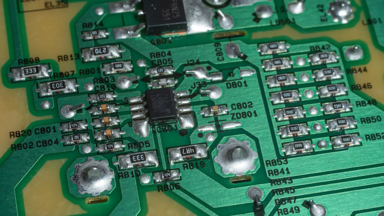
Imagine a printed circuit board with two small resistors. The solder has bridged the pads of the resistors. The bridge does not touch the metal on the resistor body. It is just a small amount of solder between the two pads.
At Level 1, this may be acceptable if the bridge is small and does not create a short. The inspector may note it but allow the board to pass. At Level 3, this is a reject. The solder must be removed and the joint redone. The bridge creates a risk of future shorts, especially if the board is subjected to vibration or thermal stress.
This example shows why the quality level matters. The same physical defect is acceptable in one context and unacceptable in another. The standard gives both parties a clear line. It also gives the supplier a reason to fix the process. If Level 3 rejects are common, the soldering process is not reliable enough for that quality tier.
How the Standard Relates to Other Rules
The IPC-A-610 standard works alongside other requirements. RoHS limits hazardous substances in the solder paste and components. UL and IEC standards address safety testing for finished products. CE marking requires conformity with specific European directives.
A board can meet IPC-A-610 and still fail a safety test. It can meet a safety test and still have a weak solder joint. The standard is one part of the quality stack. It focuses on the visible quality of the soldering process. Other standards address materials, safety, and environmental rules.
For a professional buyer, the practical step is to list all requirements in one place. The quality level for solder joints. The material restrictions for solder. The safety standard for the finished device. The environmental compliance for the region of sale. This list becomes the basis for supplier selection and acceptance testing.
Common Mistakes in Applying the Standard
One mistake is treating the standard as a checklist without understanding the intent. The standard includes images and notes. An inspector who only looks at the images may miss the reasoning behind a limit. The limits exist to reduce failure modes. Understanding the failure mode helps the inspector make consistent calls.
Another mistake is mixing levels. A buyer may ask for Level 3 on a high cost part but Level 1 on a low cost part. This is sometimes practical, but it requires clear documentation. If the same line produces both, the process must be controlled so that the Level 3 part is not accidentally treated with Level 1 tolerance.
A third mistake is relying on a single inspector. Human judgment varies. A trained inspector can still make errors. The standard helps reduce variation, but it does not eliminate it. Many companies use multiple inspectors, or automated optical inspection, to reduce risk. The standard still defines what the final human decision must be.
How to Verify the Standard Is Being Followed
Verification starts with documents. The supplier should provide a quality plan or inspection procedure that references the IPC-A-610 standard. It should state the quality level and the sampling plan. If the supplier claims to follow the standard, the documents should show it.
During audits, ask for recent inspection records. Look for defect reports. Look for rework logs. If a supplier has high rework rates, the issue may be upstream in the soldering process, not just in final inspection. The standard is a target. The process must be capable of hitting it.
For ongoing compliance, include the standard in supplier scorecards. Track defect rates by category. Track customer returns that are linked to solder joint failures. If the data shows a trend, the supplier and the buyer can address the root cause together. The standard gives you the vocabulary to have that conversation.
Final Thoughts for Engineers and Quality Managers
The IPC-A-610 standard is a practical tool. It gives engineers and quality managers a shared reference for solder joint quality. It helps define what is acceptable before production starts. It reduces disputes during inspection. It supports a clearer link between process control and field reliability.
The standard is not the whole picture. It does not cover every aspect of electronics assembly. But it is a core part of the quality system for most board level products. If you are buying assembly, or if you are running a factory, the question of which quality level to use should be answered early. The answer shapes cost, risk, and acceptance.
Frequently asked questions
Can I use the IPC-A-610 standard for through hole components?
Yes, the standard covers through hole solder joints as well as surface mount. The acceptance criteria differ for each type, but the same quality level system applies.
Does the standard define how many defects are allowed per board?
No, it defines whether a specific defect is acceptable at a given quality level. The number of defects allowed per board is usually set in the contract or quality agreement.
Is the standard only for final inspection?
It is most commonly applied at final inspection, but it can be referenced during in-line checks. The standard itself is a visual acceptance reference, not a process control document.
What if a defect is not clearly shown in the standard?
The inspector should use engineering judgment based on the intent of the standard. If the defect could affect reliability, it should be rejected or escalated for review.
How does the standard handle solder paste defects?
The standard focuses on the finished solder joint. Solder paste defects are usually covered by the process before the solder is melted. If they result in a poor joint, the joint is evaluated under the standard.